July 7, 2017
I've decided to put this project on hold, complete some simpler projects, and build up to this one. The LD20 is still a definite goal - but I want to do it well! The first of the simpler projects is just software: a vintage microcomputer emulator.
January 24, 2014
Since last time…
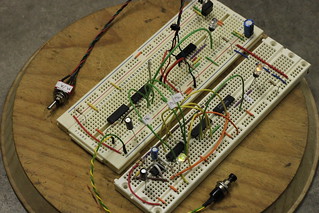
- I've tweaked the prototype system clock to include its own voltage regulator. Here's the updated circuit diagram.
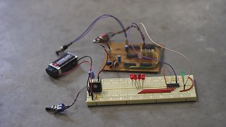
- I've put together one of the 12-bit LED display drivers. Here's the circuit diagram.
- I've screwed the whole lot to a lovely bit of wood. You know… till later.
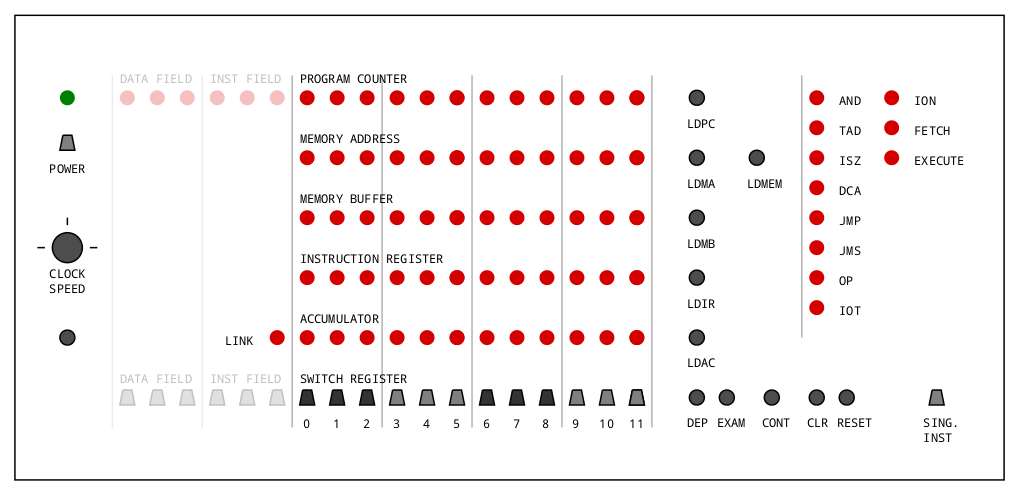
Here's roughly what I expect the front panel to look like, but it'll change as I figure things out. The ghosted out section makes space for future memory expansion controls.
January 7, 2014
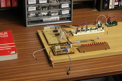
Here are the beginnings of a PDP-8 compatible LD20 minicomputer as described in The Art of Digital Design: An Introduction to Top-down Design
by Prosser and Winkel (2nd edition, 1987).
The LD20 was based on the 74LS TTL family of integrated circuits, so most components are still common.
The only rare part looks to be the 6147
4K x 1-bit static RAM chip — the memory unit described in the book uses twelve of those.
An alternative might be two 32K x 8-bit chips, such as the 62256. That is, using 8 bits of one chip and 4 of the other to make up the LD20's 4K of 12-bit words.
I expect my LD20 will take at least a couple of years to finish.
My first step is the prototype system clock, below, with manual and automatic modes. I don't have a background in electronics, so this is a special step: I'm telling myself that if I coped with the clock, I can cope with an LD20!
Here's the clock's circuit diagram, made using Inkscape.

So far, apart from the RAM chips, I've had no trouble finding parts locally (Christchurch, New Zealand: Jaycar, Global PC, South Island Component Centre) or nearby (Australia: Futurlec).
Elsewhere
- Steve Gibson's DEC PDP-8 page
- David Gesswein, Online PDP-8 Home Page [mirror]
- Vince Slyngstad's PDP-8 Stuff
- Douglas W. Jones, The Digital Equipment Corporation PDP-8 (incl. FAQ and Programmer's Reference Manual)
- The PDP-8 Archive
- Sunsite computer history archive
- D Bit public FTP archive
- PDP-8.org
- Steve Loboyko's PDP-8 clone
- Another PDP-8 clone in progress
- Intersil 6100